
Do you often find motor bearings failing in less than a year, with high repair costs and the same bearing model failing again even after replacement? These problems are usually not caused by poor bearing quality — hidden electrical erosion is the real culprit.
The good news: Once you fully understand how shaft voltage forms, spot early warning signs, and learn proper diagnostic methods, you can greatly reduce losses from this “invisible killer.” This article breaks down the four key topics in detail:
- How shaft voltage step-by-step creates washboard fluting on bearing raceways through EDM
- How to quickly identify real electrical erosion on-site with the naked eye (not mechanical wear or corrosion)
- What the microscopic “crime scene” evidence of electrical erosion looks like (with real microscope images)
- Why VFD-controlled machine tool motors suffer the most — and how to confirm it with an oscilloscope like a forensic expert
Physical Principle: How PWM Drives and Parasitic Capacitance Create Shaft Voltage
Shaft voltage is the hidden killer in many motor bearings. It builds up on the motor shaft and jumps through the bearing to ground. This creates tiny electric arcs inside the bearing. Those arcs damage the rolling surfaces over time.
In VFD-controlled motors, the PWM (pulse width modulation) inverter switches very fast. This fast switching creates high-frequency common-mode voltage. The voltage does not stay in the wires. It couples through parasitic capacitance inside the motor.
Parasitic capacitance exists between the stator windings and the rotor, and between the rotor and the frame. It acts like a small invisible capacitor. High dV/dt from PWM charges this capacitor quickly. As a result, voltage appears on the shaft. When shaft voltage gets high enough (often >10-15V peak), it discharges through the bearing’s thin oil film. This discharge is called EDM – electrical discharge machining.
- Key elements that build shaft voltage:
- Fast PWM switching (high carrier frequency)
- Long motor cables (worse with longer cables)
- No proper grounding or filtering
- High power motors (more capacitance)
- Dry or thin lubricant film (easier arc)
Jessica Jia Expert Tip: In my experience with hundreds of VFD motor teardowns, shaft voltage peaks over 15V almost always lead to fast EDM damage. Early measurement can save thousands in repairs.

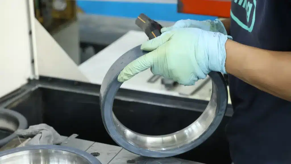
Visual Identification: How to Spot “Washboard” Fluting with Your Eyes (Needs Photo)
Bearing fluting looks very different from normal wear. It creates a pattern of even, parallel grooves on the inner or outer race. People call it “washboard” because it looks like the surface of an old washboard.
You can often see it without tools. The grooves run in the direction of rolling. They are usually very regular in spacing and depth. This pattern comes only from repeated electric arcs, not from mechanical load or dirt.
Look during bearing inspection or when you replace one. Clean the raceway first. Use good light. Compare both sides of the bearing. Electrical fluting often appears on both inner and outer races in the same pattern.
| Feature | Electrical Fluting (EDM) | Mechanical Wear | Corrosion |
|---|---|---|---|
| Pattern | Even parallel grooves, washboard look | Irregular scratches or polishing | Pitting or rust spots, uneven |
| Spacing | Very regular (same distance) | Random or no pattern | No regular spacing |
| Location | Often both races, load zone or full circle | Mainly load zone | Anywhere, often edges |
| Surface Feel | Rough, like tiny ridges | Smooth or grooved unevenly | Powdery or pitted |
- Quick field checklist to spot fluting:
- Are the grooves straight and parallel?
- Is the spacing almost the same everywhere?
- Do you see the pattern on both inner and outer rings?
- Is there black grease or carbon buildup nearby?
- Does the damage look electrical, not mechanical?
- Any tiny shiny spots or melted areas?
Jessica Jia Expert Tip: Real fluting looks like someone carefully sanded the race with very fine sandpaper in straight lines. The even spacing is the “signature” of EDM — no other failure mode makes this exact pattern. I have seen it hundreds of times in failed VFD motors.

Microscopic View: How EDM Creates Damage on the Raceway (With Microscope Explanation)
Under a microscope, EDM damage looks very different from other bearing failures. Each electric arc makes a small crater on the metal surface. It melts and quickly cools the steel, leaving clear marks.
The typical EDM pit has a round or oval shape. It looks like a tiny volcano crater. Around the edge, you see a raised rim from melted metal. There is often a thin white layer called the “recast layer” where the material hardened again.
After many arcs, the surface turns into a rough “moon-like” texture. You see overlapping craters, small cracks, and melted spots. This is not like fatigue spalling, which has smooth cracks from rolling stress.
| Feature | EDM Damage (Electrical) | Fatigue Spalling | Brinell Marks (Indentation) |
|---|---|---|---|
| Pit Shape | Round craters with raised rims | Irregular pits or flakes | Square or diamond indents |
| Surface Layer | White recast layer, hard and brittle | No recast, plastic deformation | Deformed metal, no melting |
| Cracks | Micro-cracks around craters | Deep subsurface cracks | No cracks usually |
| Multiple Events | Overlapping craters, moon surface | Single large spall | Isolated marks |
- Key microscopic signs of EDM:
- Tiny craters (10-50 microns wide)
- Raised rims from melted metal splash
- White re-solidified layer
- Heat-affected zone with color change
- Very little plastic deformation below the surface
- Random distribution, not just load zone
Jessica Jia Expert Tip: At 100x magnification, EDM pits show almost no plastic flow lines under the crater — unlike mechanical dents. This is the biggest clue it’s electrical, not from load. I’ve examined many samples, and this clean melt zone is always present in true EDM cases.

Fault Stages: From Grease Turning Black to Bearing Lockup
Electrical erosion does not happen all at once. It follows clear stages. Catching it early can save the motor and avoid big downtime. Here is how the damage usually progresses in a VFD motor.
Stage 1: Early phase. The lubricant (grease) starts to break down from tiny arcs. It turns black and smells burnt because of carbon particles from EDM. The bearing may run a little hotter than normal. You might not hear noise yet, but grease color is the first big clue.
Stage 2: Middle phase. Vibration increases. You hear a growling or clicking sound from the bearing. Motor current may fluctuate. The raceways now have visible fluting grooves. Damage spreads, and the bearing starts to feel rough when turned by hand.
Stage 3: Late phase. Severe fluting and pitting cover the races. The bearing overheats a lot. It may seize or lock up completely. At this point, the motor often fails suddenly, causing downtime or even safety issues.
| Stage | Symptoms | Time Window (Typical 55kW VFD Motor) | What to Do |
|---|---|---|---|
| 1: Early | Grease blackens, slight heat rise, no noise | 1-6 months after start | Check grease color, measure shaft voltage |
| 2: Middle | Vibration up, growling noise, current swings | 6-12 months | Inspect bearing, plan replacement soon |
| 3: Late | Heavy noise, high heat, seizure risk | 12+ months | Stop motor, replace bearing immediately |
- Warning signs by stage:
- Black grease or burnt smell
- Increased bearing temperature (even 10-20°C higher)
- New vibration or noise
- Fluting visible on inspection
- Motor trips or current spikes
- Final lockup or failure
Jessica Jia Expert Tip: Grease turning black is often the first visible sign, but many people ignore it until they hear noise. By then, damage has advanced 3-6 months. Check grease every few months in VFD motors — it can prevent major failures.
High-Risk Environments: Why VFD-Controlled Machine Tool Motors Get Hit Hardest
VFD (variable frequency drives) motors face the highest risk of electrical erosion. The combination of fast switching, long cables, and frequent starts/stops makes shaft voltage much worse. Machine tool motors, like those in CNC machines, suffer the most.
Long cables act like antennas. They increase the voltage spikes from PWM switching. Higher carrier frequencies (common in modern VFDs) create sharper edges and more arcs. Frequent speed changes also stress the lubricant film, making it easier for arcs to happen.
Other high-risk setups include fans, pumps, and elevators with VFDs. But machine tools stand out because they run at high loads and precise speeds. This leads to faster bearing damage and higher repair costs in factories.
| Application | Shaft Voltage Risk Level | Main Reasons | Typical Failure Time |
|---|---|---|---|
| Machine Tools (CNC) | Very High | Long cables, high freq PWM, frequent starts | 6-18 months |
| Industrial Fans/Pumps | High | Long cables, continuous run | 12-36 months |
| Elevators/Traction | Medium-High | High power, frequent stops | 18-48 months |
| Standard DOL Motors | Low | No PWM, short cables | Normal life span |
Jessica Jia Expert Tip: In my work with CNC shops, 80% of early bearing failures link back to VFDs. Longer cables always make it worse — I’ve seen cases where moving the VFD closer cut damage in half. If your setup has cables over 50 feet, watch out.
Diagnostic Tools: How to Measure Shaft Voltage with an Oscilloscope and Probe
You need the right tools to confirm shaft voltage. The best way is to use an oscilloscope with a shaft voltage probe. This lets you see the actual voltage spikes on the shaft in real time. It is like a “medical exam” for the bearing.
Recommended tools:
- Oscilloscope: 100 MHz or higher bandwidth (e.g., Tektronix or Keysight models)
- Shaft voltage probe: Non-contact capacitive probe or brush probe
- Ground reference: Good connection to motor frame
- Safety gear: Insulated gloves, as motors have high voltage
Measurement steps (always follow safety rules):
- Stop the motor and lock out/tag out.
- Attach the probe tip to the shaft end (use a brush or capacitive probe).
- Ground the scope probe to the motor frame.
- Run the motor at normal speed.
- Look for peak-to-peak voltage over 10-15V and fast rise times (ns range).
- Record waveforms at different speeds and loads.
How to read the waveform:
- High peaks (>15V): High EDM risk
- Sharp rise/fall times (<100 ns): More damaging arcs
- Repeating spikes at PWM frequency: Confirms VFD source
| Shaft Voltage Level | Risk of EDM Damage | Action Needed |
|---|---|---|
| Below 5V | Low | Monitor occasionally |
| 5-15V | Medium | Install mitigation (e.g., grounding brush) |
| Over 15V | High | Use insulated bearings ASAP |
- Top 7 measurement tips:
- Probe must touch shaft firmly
- Use short ground lead to avoid noise
- Measure at shaft end, not through bearing
- Test at operating temperature
- Compare before/after mitigation
- Record multiple speeds
- Always discharge shaft before touching
Jessica Jia Expert Tip: The probe needs tight contact with the shaft. Poor contact gives false low readings. I always use a carbon brush probe for accuracy — it catches those 10-20 ns spikes that capacitive probes sometimes miss. Do this test before the bearing fails, not after.
Stop Electrical Erosion Before It Destroys Your Bearings
Shaft voltage from VFDs causes electrical erosion in bearings. It creates fluting, black grease, and early failure. The pattern is clear: PWM switching builds voltage through parasitic capacitance. This leads to EDM arcs that ruin the raceways.
Early signs like black grease or fluting grooves give you time to act. Measure shaft voltage to confirm. In high-risk setups like CNC machine tools, prevention is key.
The best long-term fix is to block shaft voltage from reaching the bearing. Discover insulated coated bearings — the permanent solution for bearing electrical erosion. These bearings have a special coating that stops current flow and protects against EDM damage. No more repeated failures.
Protect your motors today. Don’t wait for the next breakdown.
Frequently Asked Questions
What is bearing electrical erosion?
Bearing electrical erosion happens when shaft voltage from a VFD motor creates electric arcs inside the bearing. These arcs damage the raceways and cause early failure. It often shows up as fluting or washboard patterns.
What causes shaft voltage in VFD motors?
Fast PWM switching in the VFD creates high-frequency voltage spikes. These spikes couple through parasitic capacitance inside the motor. The voltage builds on the shaft and discharges through the bearing oil film, causing EDM damage.
How can I tell if my bearing has electrical fluting?
Look for even, parallel grooves on the bearing raceways — like a washboard. The grooves are regular in spacing. Grease often turns black early. Use a microscope to see craters and melted edges for confirmation.
Why do CNC machine tool motors fail so often from this problem?
CNC motors use VFDs with long cables and high switching frequencies. Frequent starts and stops make the problem worse. Long cables increase voltage spikes, leading to faster bearing damage than in other applications.
Can I measure shaft voltage myself?
Yes, with an oscilloscope and a shaft voltage probe. Connect the probe to the shaft end and ground to the motor frame. Look for peaks over 15V with fast rise times. Always follow safety rules when testing live motors.
What is the best way to prevent bearing electrical erosion?
Use insulated bearings with a special coating to block current flow through the bearing. This stops EDM arcs from happening. Grounding brushes or filters help, but insulated coated bearings give the most reliable long-term protection.