
Ceramic-coated bearings have become a cornerstone technology for preventing electrical damage in modern electric motors, generators, and EV drivetrains. Instead of allowing shaft currents to arc through steel raceways, a thin ceramic layer on the bearing ring creates a high-resistance barrier that blocks current while still carrying mechanical loads. Understanding thickness, hardness, and dielectric strength is essential for selecting the right coated bearing and for explaining why premium electrically insulated bearings outperform low-cost alternatives.
Why Bearings Use Ceramic Coatings
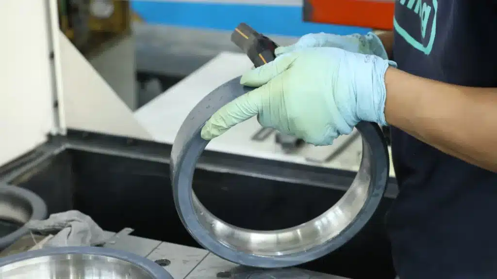
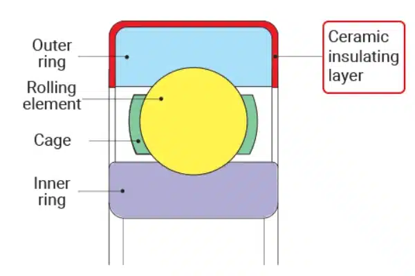
Inverter-driven motors and high-voltage drives generate common-mode voltages that can push current through the rolling contact zone. Those tiny but frequent discharges cause electrical pitting, fluting, lubricant carbonization, and early failure. A ceramic coating, typically alumina (Al2O3), applied by plasma spraying, electrically isolates the bearing ring from its mating component, breaking that current path and protecting the bearing surfaces.
Ceramic-coated bearings are widely used in:
- VFD-driven industrial motors and pumps
- Wind turbine generators and large alternators
- Traction motors in rail and EV applications
- Motors in corrosive or high-humidity environments, where coatings also add corrosion resistance
Because the mechanical design of the bearing remains standard, coated bearings are usually “drop-in” replacements, dimensionally compatible with conventional units.
Ceramic Coating Thickness: Not Too Thin, Not Too Thick
Typical Thickness Ranges
Most electrically insulated bearings use coating thicknesses in the range of roughly 50-200 micrometers (µm) on the coated ring. A coating around 100 µm is commonly specified to provide insulation up to about 1000 V DC in many industrial applications. Thicker coatings, around 200 µm or more, are used for higher-voltage or harsher environments, often rated up to 2000 V or beyond.
Why Thickness Matters
Insulation Performance
Thickness contributes directly to breakdown voltage and creepage distance. Up to a point, a thicker dielectric layer withstands higher voltages and offers more margin against partial discharge and surface contamination.
Dimensional Accuracy and Fit
Coatings add material on the ring surface. If the coating is too thick or uneven, the bearing’s outside diameter or bore can drift outside tolerance, affecting shaft or housing fits. This can lead to improper interference, assembly problems, or altered internal clearance.
Heat Transfer and Temperature
Ceramics have much lower thermal conductivity than bearing steel. Excessively thick coatings can impede heat flow from the bearing into the housing, raising operating temperatures and accelerating lubricant degradation.
Mechanical Stresses and Adhesion
Thicker layers carry higher internal stresses and are more prone to cracking or spalling under impact or heavy vibration. Very thin layers, on the other hand, may not fully cover pores and asperities, leaving pinholes and weak spots.
Finding the “Optimal” Thickness
The best coating thickness is a trade-off between:
- Required breakdown voltage and insulation life
- Dimensional tolerances of shaft and housing
- Operating temperature and cooling capability
- Load, shock, and vibration levels
- Environmental factors like humidity, salt spray, or chemicals
For typical VFD motors, coatings around 100-200 µm on the outer or inner ring often balance these factors well. Lower-voltage, space-constrained applications might use thinner coatings, while high-voltage or corrosive installations may justify 200-300 µm or more.
Hardness and Wear: Protecting the Coated Ring
What Hardness Tells You
Ceramic coatings are much harder than bearing steel. Hardness is often expressed in Vickers (HV). Coating hardness can be roughly 1300-1500 HV10 for dense alumina layers, compared with around 700 HV10 or less for hardened bearing steel. This high hardness gives the coating excellent wear resistance against abrasive particles and micro-sliding.
However, hardness alone is not enough. Other important properties include:
- Adhesion strength between coating and steel substrate
- Toughness and resistance to cracking
- Residual stress in the coating from the spray process
A very hard but brittle, poorly bonded coating may chip, crack, or flake under shock loads or misalignment.

How Hardness Affects Bearing Performance
- Wear and Corrosion Resistance: Hard ceramic is resistant to abrasion and many corrosive environments, extending bearing life where dust, salt spray, or moisture are present.
- Fretting and Micromovement: In fits where some micro-movement occurs, a harder coated ring resists fretting wear better than bare steel.
- Contact with Rolling Elements: The rolling elements typically contact the uncoated raceways, not the coated surface. But where coating overlaps near shoulders or edges, too brittle a layer can chip and create debris.
High-quality coatings balance very high hardness with controlled porosity, residual stress, and strong bonding so they survive long-term vibration and thermal cycling.
Dielectric Strength: How Coatings Block Electrical Damage
Dielectric Strength vs. Insulation Resistance
Two related but distinct properties describe electrical capability:
- Insulation resistance (IR): The resistance in megaohms or gigaohms when a DC test voltage (e.g., 500 V) is applied between the inner and outer rings. High IR indicates low leakage current.
- Dielectric strength: The maximum electric field the coating can withstand before breakdown. It is often quoted as a breakdown voltage at a specified thickness (for example, 1000 V DC for a 100 µm coating).
A well-made alumina coating typically has very high resistivity and dielectric strength, allowing a relatively thin layer to withstand industrial voltages seen in VFD applications.
What Determines Dielectric Strength
Dielectric strength of the coated bearing depends on:
- Material purity and phase of the ceramic (alumina quality, stabilizers, etc.)
- Porosity and microcracks from the spray process
- Coating thickness and uniformity
- Sealant or topcoat used to close surface pores and improve creepage performance
- Operating environment – moisture, dirt, and conductive films decrease adequate strength
Once the coating is thick enough to meet the required breakdown voltage with margin, further increases in thickness bring diminishing returns electrically while increasing weight and stress.
Matching Dielectric Strength to Application
For a given motor:
- Estimate or measure peak shaft voltage and common mode stress from the inverter.
- Select an insulated bearing with a dielectric rating comfortably above that value.
- In high-voltage or mission-critical systems, choose coatings and geometries with extra creepage distance and robust sealing.
Coated vs. Hybrid and Full-Ceramic Bearings
Ceramic coatings are one of several electrical-protection approaches:
- Coated steel bearings (insulated bearings): Standard steel rings and balls, with a ceramic layer on the inner or outer ring. Provide high resistance and are the most common, cost-effective solution for many motors.
- Hybrid bearings: Steel rings with full ceramic balls. Electrical isolation happens through the rolling elements. They are ideal for very high speeds and high dv/dt environments, but usually cost more.
- Full-ceramic bearings: Rings and balls are all ceramic. They offer maximum insulation and corrosion resistance but have different mechanical and thermal characteristics and are used mainly in specialized applications.
For most industrial VFD motors, ceramic-coated steel bearings offer the best compromise of cost, availability, and performance, especially when the coating’s thickness, hardness, and dielectric properties are optimized for the application.

Practical Selection Guidelines for Ceramic-Coated Bearings
Define Electrical Requirements
- Expected peak shaft voltage and common mode stresses
- Presence of harmonics or fast switching causing steep dv/dt
- Regulatory or OEM requirements for insulation voltage rating
Choose a coating system whose specified breakdown voltage and insulation resistance exceed those demands with adequate safety margin.
Consider Mechanical and Thermal Loads
- Radial and axial load, speed, and shock/vibration levels
- Available cooling and typical operating temperatures
- Shaft and housing fits and required internal clearance
These parameters influence whether a thicker or thinner coating is appropriate and whether a coated outer ring, inner ring, or hybrid design is best.
Account for Environmental Conditions
- Humidity, condensation, or water exposure
- Chemical or salt-spray attack
- Dust, abrasive particles, or process contamination
In harsh conditions, slightly thicker, denser coatings with good sealing layers can provide not only insulation but also improved corrosion and wear protection.
Verify Quality and Testing
For critical applications, specify:
- Minimum coating thickness and tolerance window
- Minimum insulation resistance at a given DC test voltage
- High-potential (hipot) or breakdown tests carried out by the manufacturer
- Adhesion, hardness, and porosity criteria backed by process certificates
Incoming inspection can include sample insulation-resistance tests and visual checks for chips, cracks, or exposed steel on the coated ring.
Popular Electrically Insulated Bearing Model List
When sourcing replacements for VFD motors, it is crucial to use the complete model designation. Below is a list of the most frequently requested insulated bearings in the industrial market. These models typically feature C3 clearance (standard for electric motors) and a ceramic coating on the outer ring (commonly referenced by the suffix VL0241 or J20AA).
Table 1: Deep Groove Ball Bearings (Insulated Outer Ring)
| ISO Basic Model | Full Model Number | Dimensions (d x D x B mm) | Application |
| 6210 | 6210-C3VL0241 | 50 x 90 x 20 | Medium electric motors, fans |
| 6212 | 6212-C3VL0241 | 60 x 110 x 22 | General purpose motors |
| 6216 | 6216-C3VL0241 | 80 x 140 x 26 | Process pumps, conveyors |
| 6220 | 6220-C3VL0241 | 100 x 180 x 34 | Heavy duty industrial fans |
| 6310 | 6310-M-C3VL0241 | 50 x 110 x 27 | Traction motors (Brass Cage) |
| 6314 | 6314-C3VL0241 | 70 x 150 x 35 | VFD-driven compressors |
| 6316 | 6316-M-C3VL0241 | 80 x 170 x 39 | Wind turbine generators |
| 6322 | 6322-M-C3VL0241 | 110 x 240 x 50 | Large kilowatt motors |
| 6326 | 6326-M-C3VL0241 | 130 x 280 x 58 | Mining & crusher motors |
| 6330 | 6330-M-C3VL0241 | 150 x 320 x 65 | Heavy traction & propulsion |
Table 2: Cylindrical Roller Bearings (Insulated Outer Ring)
| ISO Basic Model | Full Model Number | Dimensions (d x D x B mm) | Application |
| NU 210 | NU 210-ECP-C3VL0241 | 50 x 90 x 20 | Belt drives (Drive End) |
| NU 214 | NU 214-ECP-C3VL0241 | 70 x 125 x 24 | Medium load radial applications |
| NU 220 | NU 220-ECM-C3VL0241 | 100 x 180 x 34 | Heavy duty pump motors |
| NU 310 | NU 310-ECM-C3VL0241 | 50 x 110 x 27 | High vibration environments |
| NU 316 | NU 316-ECM-C3VL0241 | 80 x 170 x 39 | Rail traction motors |
| NU 320 | NU 320-ECM-C3VL0241 | 100 x 215 x 47 | Steel mill motors |
| NU 324 | NU 324-ECM-C3VL0241 | 120 x 260 x 55 | Large wind generators |
| NU 330 | NU 330-ECM-C3VL0241 | 150 x 320 x 65 | Heavy industrial drives |
Note on Suffixes: “VL0241” is the most common industry standard code for Aluminum Oxide coating on the outer ring. “M” or “ECM” denotes a machined brass cage, which is preferred for high-vibration and heavy-duty applications. TFL Insulated Bearings offers full interchangeability with these specifications.
Installation and Handling Tips
Even the best ceramic coating can be compromised by poor handling:
- Avoid impacts, strikes, or prying against coated surfaces; use proper tools and press fits on uncoated faces.
- Keep coatings clean and dry; avoid dragging bearings over hard surfaces that could scratch the layer.
- Follow manufacturer recommendations for heating during mounting (induction heaters) to prevent thermal shock.
- Do not grind or machine the coated surface; it is engineered to final dimensions from the factory.
Proper handling ensures the designed electrical and mechanical properties remain intact through installation and early operation.
Ceramic coatings transform standard bearings into high-performance, electrically and mechanically robust components by combining the right thickness, hardness, and dielectric strength. When thickness is optimized, the coating delivers reliable voltage withstand without compromising fits or heat transfer. Appropriate hardness and strong adhesion ensure the layer survives vibration, load, and thermal cycling without cracking, while high dielectric strength prevents shaft currents from reaching the rolling contact zone. Together, these properties help reduce electrical pitting and fluting, extend bearing life, and improve the reliability of VFD-driven and high-voltage motor applications.
Partner with TFL Insulated Bearings for Superior Motor Protection
At TFL Insulated Bearings, we understand that the difference between a reliable motor and a costly breakdown often comes down to microns of ceramic protection. We have mastered the balance of coating thickness, hardness, and dielectric strength to provide you with bearings that withstand the harshest electrical environments.
Whether you need a drop-in replacement for a VFD pump or a custom solution for a wind turbine generator, we ensure every bearing meets rigorous quality standards before it leaves our facility. Don’t let shaft currents compromise your operations.
Ready to secure your equipment’s reliability?
- Email Us: Send your inquiries or technical questions to info@sdtflbearing.com.
- Call Us: Speak directly with our engineering team at +86 15806631151.
- Get a Quote: Click the sidebar popup to chat with an agent instantly.
- Contact us: Fill out the form to request our full catalog of insulated bearing models.