
Electrical erosion in bearings is one of the most common hidden causes of premature motor and generator failure in today’s inverter-driven world. Stray shaft voltages silently discharge through rolling elements, creating microscopic burns that slowly destroy raceways and lubricants. By the time noise and vibration are obvious, the bearing is often near the end of its life. Detecting electrical erosion early-before catastrophic failure-is therefore essential for reliability engineers, maintenance teams, and OEMs designing high-availability systems.
Understanding Electrical Erosion in Bearings
What Is Electrical Erosion?
Electrical erosion occurs when an electric current passes through the bearing instead of following a designed path to ground. A thin lubricant film usually separates rolling elements from raceways. Electrically, that film behaves like a capacitor. When the shaft voltage rises high enough, this “capacitor” breaks down and discharges in the form of a tiny spark between metal surfaces.
Each discharge instantaneously melts and vaporizes a microscopic volume of steel. Over millions of events, this process-often called Electrical Discharge Machining (EDM)-produces:
- Electrical pitting: small craters and a frosted texture on raceways.
- Fluting: washboard-like grooves along the rolling path caused by repeated contact over damaged areas.
These defects increase friction, noise, and vibration, and eventually lead to spalling, overheating, and bearing seizure.

Why Modern Drives Increase the Risk
Frequency converters and inverters use high-frequency pulse-width modulation (PWM) to control motor speed. The steep voltage edges and asymmetries in the system create common-mode voltages between rotor and stator. If no effective mitigation is in place, these voltages drive currents through the bearings, especially when:
- Motors are fed by long cables or poorly shielded leads.
- Switching frequencies are high and dv/dt is steep.
- Grounding and bonding of the motor, frame, and drive are inadequate.
Early Warning Signs of Electrical Erosion
Changes in Noise and Vibration
Noise and vibration are often the first symptoms operators notice:
- A high-frequency whine or hiss that changes with speed.
- Increased broadband vibration or new peaks at bearing defect frequencies, especially outer race frequencies (BPFO) and their harmonics.
Vibration data with rising bearing-related frequencies, combined with a known risk environment (VFD, long cables), is a strong indicator of emerging electrical erosion.
Localized Temperature Rise
Electrical discharges and roughened surfaces raise friction and bearing temperature. Infrared checks or built-in sensors may show:
- Bearing housings running hotter than similar motors under comparable load.
- Gradual temperature increases over time that cannot be explained by load or ambient conditions alone.
While temperature alone does not prove electrical erosion, it reinforces other clues.
Lubricant Condition Changes
Grease or oil exposed to repeated arcing:
- Darkens or appears burnt or carbonized near the raceways.
- May contain unusually fine metallic particles from pitted steel surfaces.
Regular lubricant inspections, therefore, provide another proper early warning channel.
Diagnostic Techniques for Electrical Erosion
Shaft Voltage and Discharge Detection
The most direct diagnostic approach is to measure shaft voltage and observe discharge behavior:
- A conductive probe or brush contacts the rotating shaft while voltage to ground is monitored.
- Oscilloscope traces showing repetitive peaks and sharp, needle-like spikes indicate discharge events through the bearings.
Because this setup can be complex and intrusive, it is typically used on critical assets during commissioning or for specialized troubleshooting.
Newer handheld devices can detect the magnetic field changes caused by each discharge. These tools count discharge events and provide a rapid yes/no indication of electrical erosion without direct electrical contact with the shaft.
Vibration and Spectrum Analysis
Condition monitoring systems detect electrical erosion through characteristic patterns in vibration data:
- Appearance of bearing defect frequencies (BPFO, BPFI, BSF, FTF) and their low-frequency harmonics.
- Increased amplitude in high-frequency bands associated with impacting over pits and flutes.
- Envelope (demodulation) analysis revealing repetitive impacts long before the overall vibration is high.
Trended over time, these signatures provide early notice that a bearing is deteriorating due to electrical effects rather than purely mechanical causes.
Acoustic and Ultrasound Monitoring
Acoustic emission and ultrasound instruments are sensitive to the high-frequency energy from micro-arcs and impacts:
- Headset-style ultrasonic detectors can pick up subtle crackling or buzzing associated with discharges and roughened surfaces.
- Acoustic emission sensors installed on critical machines allow continuous monitoring of early damage stages.
These methods are especially valuable where complex machine dynamics may mask traditional vibration data.
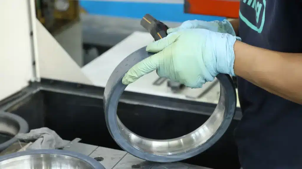
Visual Examination During Overhaul
When a bearing is removed, careful inspection can confirm electrical erosion:
- Frosted or matte raceway appearance compared with the mirror finish of undamaged bearings.
- Visible pits, craters, or fluting patterns-parallel grey bands or ridges along the rolling path.
- Dark, burnt grease in the loaded zones.
Documenting these patterns helps distinguish electrical erosion from mechanical overload, contamination, or misalignment, and informs future preventive measures.
Differentiating Electrical Erosion from Other Failures
Correct root-cause identification is essential to avoid repeat failures. Electrical erosion can be distinguished by:
- Uniform, fine pitting and washboard fluting, versus random spalls or large fatigue cracks typical of overload.
- Burnt grease and EDM craters rather than contamination-induced dents or abrasive scratches.
- Strong correlation with VFD operation, long cables, or poor grounding.
When these signatures are present, simply replacing the bearing without addressing electrical causes will almost certainly result in another early failure.

Preventing Electrical Erosion Before It Causes Catastrophic Failure
Electrically Insulated and Hybrid Bearings
One of the most effective mitigation strategies is to specify bearings designed to block current:
- Electrically insulated bearings use ceramic coatings on the inner or outer ring to provide high insulation resistance and withstand significant voltages.
- Hybrid bearings use ceramic rolling elements, which are non-conductive and interrupt the current path completely.
These designs prevent shaft currents from using the bearing as a path to ground, eliminating the need for EDM and the resulting pitting and fluting.
Common Electrically Insulated Bearing Models for VFD Motors
To effectively prevent electrical erosion, selecting the right insulated bearing size is crucial. Below is a list of commonly used electrically insulated bearing models suitable for standard motor frame sizes:
| Bearing Type | ISO Series | Common Insulated Suffixes | Typical Application |
| Deep Groove Ball Bearings | 6210 – 6230 | J20AA, J20B, VL0241 | Small to Medium Motors |
| Deep Groove Ball Bearings | 6310 – 6334 | J20AA, J20B, VL0241 | Heavy Duty VFD Motors |
| Cylindrical Roller Bearings | NU 210 – NU 230 | J20AA, J20B, VL0241 | High Load Belt Drives |
| Cylindrical Roller Bearings | NU 310 – NU 334 | J20AA, J20B, VL0241 | Large Inverter Motors |
| Hybrid Ceramic Bearings | 60xx, 62xx, 63xx | HC5, TN9/HC5 | High Speed Spindles |
(Note: Suffixes may vary by manufacturer standard, but generally indicate ceramic coating on the outer or inner ring.)
Shaft Grounding and Bonding
Insulated bearings are often combined with measures that deliberately conduct currents safely:
- Shaft grounding rings or brushes give high-frequency currents a low-impedance route to ground, bypassing bearings.
- Proper bonding between the motor frame, drive cabinet, and plant ground prevents floating potentials that would otherwise drive unwanted currents.
A common practice is to install an insulated bearing at one end of the motor and a grounding device at the other, creating a defined current path away from the rolling elements.

Inverter, Cable, and Installation Practices
Electrical erosion can be significantly reduced by:
- Using shielded motor cables and routing them to minimize stray capacitances.
- Adding dv/dt or sine-wave filters on the VFD output to reduce high-frequency voltage content.
- Adjusting switching frequency when appropriate, since higher frequencies increase the chance of discharge events.
- Following manufacturer guidelines for maximum cable length and proper grounding.
These measures lower the shaft voltage and the probability of bearing discharges.
Building a Detection and Prevention Program
Step 1: Identify High-Risk Assets
Focus attention on motors that:
- Are driven by VFDs or inverters.
- Use long or complex cable runs.
- Operate at high speed, high power, or in critical processes where failure is very costly.
Creating a register of such assets provides a starting point for targeted monitoring.
Step 2: Establish Baseline Data
For each critical motor, record:
- Baseline vibration spectra and overall levels.
- Bearing housing temperatures under typical operating conditions.
- Where possible, shaft voltage snapshots or discharge counts.
This baseline makes it much easier to recognize subtle deviations that indicate emerging electrical erosion.
Step 3: Implement Condition Monitoring
Use a combination of tools:
- Online or periodic vibration analysis with attention to bearing frequencies.
- Infrared checks or temperature sensors on bearing housings.
- Ultrasound or acoustic emission surveys on high-value assets.
- Periodic use of discharge detection pens or shaft voltage checks on suspect machines.
Anomalies should trigger more detailed investigations, such as in-depth vibration diagnostics or electrical measurements.
Step 4: Upgrade Bearings and Electrical Protection
When diagnostics or teardown confirm electrical erosion, simply installing a new standard bearing is not enough. The underlying electrical conditions must be corrected or the new bearing will fail in the same way.
Key actions include:
- Replace with electrically insulated or hybrid bearings sized and specified for the motor’s load, speed, and temperature range.
- Add shaft grounding rings or brushes on the appropriate end of the motor to provide a controlled, low-impedance return path for high-frequency currents.
- Verify grounding and bonding of the motor frame, drive enclosure, and cable shields to the plant earth grid to minimize stray potentials.
- Review VFD and cable configuration (filters, cable type, routing, and length) to reduce common mode voltage and shaft voltage levels.
Document the changes in the asset’s maintenance history so future inspections and reliability reviews can take the upgraded protection into account.
Step 5: Optimize and Standardize Your Program
Once detection and protection measures are in place, they should be formalized into a repeatable reliability program:
- Create standard specifications for all new or refurbished VFD-driven motors, including insulated bearings and shaft grounding requirements where appropriate.
- Integrate shaft voltage, vibration, and temperature checks into commissioning procedures and periodic inspections for critical assets.
- Use a centralized database or CMMS to store condition monitoring data, inspection findings, and bearing replacement details so trends and recurring issues can be analyzed.
- Provide training for technicians and engineers on recognizing electrical erosion signatures in data and in physical bearings, ensuring the root cause is correctly identified and addressed.
Over time, this approach moves the organization from reactive bearing replacement to proactive, evidence-based electrical erosion management.
Catch Electrical Erosion Before It Catches You
Electrical erosion is a silent but serious threat to bearings in modern, inverter-driven motors and generators. Stray shaft voltages and microscopic EDM discharges gradually transform smooth raceways into frosted, fluted surfaces that generate noise, vibration, and heat, and ultimately lead to catastrophic failure. The good news is that these failures are highly predictable-and preventable-when a systematic detection and prevention strategy is in place.
By combining early warning methods (vibration, ultrasound, temperature, and lubricant inspection) with targeted diagnostics (shaft voltage and discharge detection), maintenance teams can identify electrical erosion long before it leads to unplanned downtime. Upgrading to electrically insulated or hybrid bearings, adding shaft grounding, and following best practices for VFDs and cabling then removes the root cause, protecting both bearings and the broader powertrain.
Implementing these measures turns electrical erosion from a mysterious, recurring failure mode into a controllable engineering variable-extending bearing life, improving reliability, and safeguarding production against catastrophic bearing failures.
Stop Electrical Erosion with TFL Insulated Bearings
Understanding how to detect electrical erosion is the first step, but preventing it is the ultimate goal. At TFL Insulated Bearings, we specialize in protecting your critical assets from the silent destruction of stray shaft currents.
We provide high-quality electrically insulated bearings designed specifically for inverter-driven motors and generators. Our advanced ceramic coating technology ensures that your bearings block harmful currents, eliminating fluting and premature failure. Don’t wait until your vibration analysis shows a critical defect.
Ready to upgrade your reliability program?
- Contact Us: Discuss your specific motor requirements with our engineering team.
- Get a Quote: Send your inquiry directly to info@sdtflbearing.com.
- Call Us: Reach us immediately at +86 15806631151.
Protect your motors today—[Click here to contact TFL Insulated Bearings] or verify your bearing requirements via the sidebar form.