
Insulated electric bearings are a frontline defense against shaft currents, electrical pitting, and fluting in inverter-driven motors and generators. But the insulation layer-whether a ceramic coating on the rings or ceramic rolling elements-only protects the machine if its resistance stays high over time. That is why knowing how to test insulation resistance in electric bearings is essential for OEMs, maintenance engineers, and reliability teams. Proper insulation resistance (IR) testing confirms that bearings really provide the megohm-level isolation needed to keep damaging current out of the raceways.
Why Insulation Resistance Testing Matters
Insulation resistance is a measure of how effectively the bearing’s insulating layer blocks DC current between the rolling path and the grounded structure. In insulated bearings, this usually means measuring resistance between:
- The inner ring (connected to the shaft) and
- The outer ring (connected to the housing or frame).
If resistance falls too low-because of moisture, contamination, coating damage, or manufacturing defects-shaft currents can again flow through the bearing, leading to EDM damage just as if no insulation were present.

Insulation resistance testing allows you to:
- Verify incoming quality of new insulated bearings.
- Confirm insulation after motor assembly or rewinding.
- Monitor insulation health during periodic maintenance for critical assets.
Basic Principles of Insulation Resistance Testing
Insulation resistance is measured by applying a DC test voltage and measuring the resulting leakage current. Ohm’s law gives:
where R is insulation resistance in ohms (typically megohms or gigaohms), V is the applied test voltage, and I is the leakage current.

Key points:
- Higher resistance means better insulation.
- Resistance drops when insulation is contaminated, cracked, or saturated with moisture.
- Readings depend on test voltage, temperature, and test duration, so these need to be controlled or at least recorded.
Common tools:
- Megohmmeters (“megger” instruments) designed for 100 V to 1000+ V DC insulation testing.
- Dedicated insulation testers integrated into bearing or motor test benches.
Test Standards and Typical Values for Insulated Bearings
Bearing manufacturers specify minimum insulation performance for their insulated series. For example, ceramic-coated bearings often require:
- Insulation resistance ≥ several megaohms (often ≥ 50 MΩ) at a specified DC voltage (e.g., 500 V).
- Breakdown voltage is high enough to withstand standard-mode peak voltages seen in VFD applications.
Always check:
- The datasheet for the exact resistance and test voltage requirements.
- Whether the bearing is designed for inner-ring coated, outer-ring coated, or hybrid construction-this affects test wiring.
Preparing for an Insulation Resistance Test
Safety and Equipment
Before testing, ensure:
- The bearing or motor is de-energized, locked out, and tagged out.
- Capacitors and DC bus circuits are discharged if you are testing in situ on a motor.
- The test area is dry and clean to avoid surface leakage paths.
You will need:
- A suitable megohmmeter or insulation resistance tester with the correct voltage range (often 100–1000 V DC).
- Test leads with clips or probes that can firmly contact the bearing rings.
- Clean rags and solvent for removing grease or contamination from contact areas (without letting solvent into the bearing).
Isolated Component vs. Assembled Motor
Testing can be done:
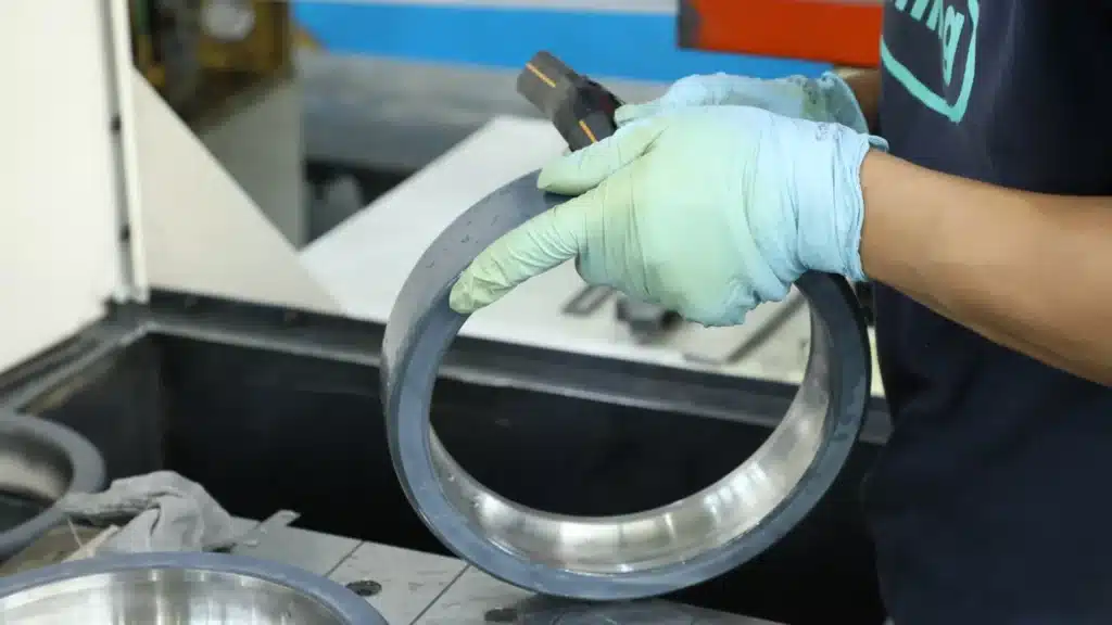
- On the loose bearing, before installation, ideal for incoming inspection.
- On the assembled motor, measuring between the shaft and frame, which also reflects any other insulation paths in series.
For precise bearing quality control, loose-bearing tests are preferred. For field checks, shaft-to-frame tests are more convenient.
Step-by-Step: How to Test Insulation Resistance in Electric Bearings
1. Visual Inspection and Cleaning
- Inspect the bearing for chips, cracks, and mechanical damage on coated surfaces.
- Wipe exposed ring surfaces clean and dry at the contact points to avoid false low readings from surface contamination.
2. Connect the Test Leads
For a loose, ceramic-coated bearing:
- Clamp one lead to the inner ring.
- Clamp the other lead to the outer ring (or housing adapter if used).
Ensure good metallic contact on non-coated surfaces or on designated test pads, as many insulated bearings have small uncoated areas for electrical contact.
For an assembled motor:
- Connect one lead to the shaft (using a clamp or brush).
- Connect the other lead to a clean grounded part of the frame.
3. Select Test Voltage
Choose the DC test voltage according to:
- Bearing manufacturer recommendations (for example, 500 V DC).
- Plant safety practices and insulation class of the system.
Do not exceed the maximum test voltage specified for the bearing insulation.
4. Apply Voltage and Measure
- Press the test button; most megohmmeters ramp up voltage automatically.
- Maintain the test for 30–60 seconds to allow the charge to stabilize and observe how the resistance value changes.
- Record the reading in megohms (MΩ) or gigaohms (GΩ).
If readings climb over time and stabilize at a high value, that is typical of healthy insulation; if they stay low or fall, insulation is likely compromised.
5. Discharge and Disconnect
After the test:
- Use the tester’s discharge function (if available) to remove stored charge.
- Wait for the instrument to indicate safe conditions, then remove leads.
- For motors, verify with a multimeter that no residual voltage remains.
Interpreting Insulation Resistance Results
Good vs. Marginal vs. Bad
Bearing vendors usually define pass/fail criteria, but standard guidelines:
- Good insulation: Resistance well above the minimum specified-for example, ≥ 100 MΩ at 500 V DC, stable or rising during the test.
- Marginal: Resistance just above the limit or highly sensitive to humidity and temperature; may warrant retest or closer monitoring.
- Bad: Resistance below the specified minimum, or readings that fluctuate erratically; bearing should be rejected or replaced.
Always account for:
- Temperature: Insulation resistance decreases as temperature rises, so compare readings taken at similar temperatures or correct using manufacturer guidance.
- Humidity and contamination: High humidity or surface moisture will depress readings; ensure surfaces are clean and dry.
Trends Over Time
For installed motors, trending is more valuable than a single measurement:
- Track IR values over months or years in a maintenance database.
- Rising currents or decreasing megohm values indicate gradual insulation deterioration and allow planned replacement before failure.

Common Testing Mistakes to Avoid
- Testing through grease or contamination: Oil or conductive contaminants on test points create parallel leakage paths and false low readings.
- Using too low a test voltage: Results may appear high but may not reflect performance at the operating voltage.
- Not isolating parallel paths: On assembled motors, other components (couplings, bearings, shaft grounding devices) may bypass the insulated bearing, confusing results.
- Ignoring temperature and humidity: Comparing readings taken in very different conditions can lead to wrong conclusions.
Following a consistent test procedure and documenting conditions avoids these pitfalls.
Integrating Insulation Resistance Testing into Your Bearing Program
Incoming Inspection for Insulated Bearings
When you receive new insulated bearings:
- Perform sample or 100% IR tests according to your quality plan.
- Record batch numbers, resistance values, and test conditions.
- Reject or quarantine bearings that fail to meet the specified insulation resistance or show highly variable readings.
This prevents defective insulation from ever reaching critical motors.
Commissioning of New Motors
At motor commissioning:
- Perform a shaft-to-frame IR test to confirm the correct installation of insulated bearings and grounding devices.
- Use the results as the baseline for future maintenance comparisons.
Any significant change from baseline later should trigger an investigation.
Periodic Maintenance on Critical Assets
For important VFD-driven motors and generators:
- Include insulation resistance tests in annual or biennial inspections.
- Combine IR testing with vibration analysis and thermal imaging to build a comprehensive view of bearing condition.
- Establish alarm and action thresholds based on manufacturer guidance and your historical data.
Focus on Safety While Testing
Insulation resistance testing involves the application of elevated DC voltages. Observe these practices:
- Only trained personnel should perform tests.
- Use PPE appropriate for the test voltage and environment.
- Keep others clear of the test area and clearly indicate that testing is in progress.
- Follow all relevant plant electrical safety policies and local regulations.
Best-Practice Checklist: Testing Insulation Resistance in Electric Bearings
- Confirm the motor or bearing is isolated, de-energized, and safe.
- Clean and dry test contact surfaces.
- Connect one lead to the inner ring/shaft and one to the outer ring/frame.
- Select the manufacturer-recommended DC test voltage.
- Apply the voltage and hold for at least 30-60 seconds.
- Record the resistance value, temperature, and humidity.
- Compare against specified minimum megohm values.
- Discharge the system and remove leads safely.
- Store results in a maintenance database for trending.
Following this checklist turns insulation resistance testing into a repeatable, auditable process.
Verifying the Shield Around Your Bearings
Electrically insulated bearings can dramatically reduce failure rates in VFD-driven motors, generators, and EV drivetrains. but only if their insulation layer performs as designed throughout the equipment’s life. Insulation resistance testing provides the proof, allowing you to verify incoming quality, validate correct installation, and monitor long-term health.
By understanding how insulation resistance works, using appropriate test voltages and procedures, and interpreting results in the context of temperature, humidity, and trends, maintenance and reliability teams can catch insulation problems early and avoid electrical erosion of bearings. Combined with good grounding practices, proper VFD cabling, and the use of high-quality insulated bearings, regular IR testing forms a robust strategy for protecting electric bearings from hidden electrical threats and keeping critical motors running reliably.
Secure Your Assets with TFL Insulated Bearings
At TFL Insulated Bearings, we understand that a robust insulation layer is the only thing standing between your critical motors and damaging shaft currents. We don’t just manufacture bearings; we provide the peace of mind that comes from knowing your equipment is protected by industry-leading isolation technology.
Whether you need to replace a failing component or upgrade your VFD-driven systems to prevent future downtime, we are here to support your reliability goals.
Ready to upgrade your motor protection?
- Contact us today for a consultation on your specific application.
- Send us an email at info@sdtflbearing.com for a quick quote.
- Call us directly at +86 15806631151.
Don’t wait for the next insulation failure—partner with TFL for bearings that pass the test every time.